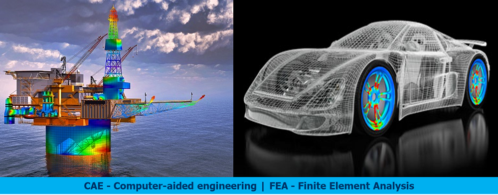
Introduction to CAE – Computer Aided Engineering | FEA – Finite Element Analysis
A Brief History of Computer Aided Engineering
Definition of CAE: Computer-aided engineering (CAE) is the broad usage of computer software to aid in engineering analysis tasks.
It includes:
- Finite Element Analysis (FEA)
- Computational Fluid Dynamics (CFD)
- Multi body dynamics (MBD)
- Optimization
While it is difficult to quote a date of the invention of the finite element method, the method originated from the need to solve complex elasticity and structural analysis problems in civil and aeronautical engineering.
Its development can be traced back to the work by A. Hrennikoff and R. Courant. In China, in the later 1950s and early 1960s, based on the computations of dam constructions, K. Feng proposed a systematic numerical method for solving partial differential equations. The method was called the finite difference method based on variation principle, which was another independent invention of finite element method. Although the approaches used by these pioneers are different, they share one essential characteristic: mesh discretization of a continuous domain into a set of discrete sub-domains, usually called elements.
- Lord John William Strutt Rayleigh (late 1800s), developed a method for predicting the first natural frequency of simple structures. It assumed a deformed shape for a structure and then quantified this shape by minimizing the distributed energy in the structure.
- Walter Ritz then expanded this into a method, now known as the Rayleigh-Ritz method, for predicting the stress and displacement behavior of structures.
- In 1943, Richard Courant proposed breaking a continuous system into triangular segments. (The unveiling of ENIAC at the University of Pennsylvania.)
- In the 1950s, a team form Boeing demonstrated that complex surfaces could be analyzed with a matrix of triangular shapes.
- Dr. Ray Clough coined the term “finite element” in 1960. The 1960s saw the true beginning of commercial FEA as digital computers replaced analog ones with the capability of thousands of operations per second.
- In the early 1960s, the MacNeal- Schwendler Corporation (MSC) develops a general purpose FEA code. This original code had a limit of 68,000 degrees of freedom. When the NASA contract was complete, MSC continued development of its own version called MSC/NASTRAN, while the original NASTRAN become available to the public and formed the basis of dozens of the FEA packages available today. Around the time MSC/NASTRAN was released, ANSYS, MARC, and SAP were introduced.
- By the 1970s, Computer-aided design, or CAD, was introduced later in the decade.
- In the 1980s, the use of FEA and CAD on the same workstation with developing geometry standards such as IGES and DXF. Permitted limited geometry transfer between the systems.
- In the 1980s,CAD progressed from a 2D drafting tool to a 3D surfacing tool, and then to a 3D solid modeling system. Design engineers began to seriously consider incorporating FEA into the general product design process.
- As the 1990s draw to a place, the PC platform has become a major force in high end analysis. The technology has become to accessible that it is actually being “hidden” inside CAD packages.
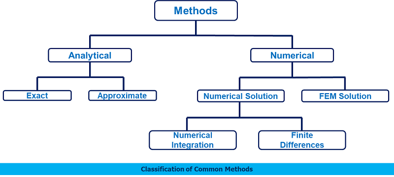
Comparison of FEA with other Methods
The common methods available for the solute=ion of genera field problems, like elasticity, fluid flow, heat transfer problems, etc. can be classified as presented in below fig.
 Finite Element Analysis or Finite Element Method:
Finite element analysis (FEA) involves solution of engineering problems using
Computers. Engineering structures that have complex geometry and loads, are either very difficult to analyze or have no theoretical solution. However, in FEA, a structure of this type can be easily analyzed. Commercial FEA programs, written so that a user can solve a complex engineering problems without knowing the governing equations or the mathematics; the user is required only to know the geometry of the structure and its boundary conditions. FEA software provides a complete solution including deflections, stresses, reactions, etc.
In order to become a skillful FEA user, a thorough understanding of techniques for modeling a structure, the boundary conditions and, the limitations of the procedure, are very crucial. Engineering structures, e.g., bridge, aircraft wing, high-rise buildings, etc., are examples of complex structures that are extremely difficult to analyze by classical theory. But FEA technique facilitates an easier and a more accurate analysis. In this technique the structure is divided into very small but finite size elements (hence the name finite element analysis). Individual behavior of these elements is known and, based on this knowledge; behavior of the entire structure is determined.
FEA solution of engineering problems, such as finding deflections and stresses in a Structure, requires three steps:
- Pre-process or modeling the structure
- Analysis
- Post processing
Step1: Pre-process or modeling the structure:
Using a CAD program that either comes with the FEA software or provided by another software vendor, the structure is modeled. The final FEA model consists of several elements that collectively represent the entire structure. The elements not only represent segments of the structure, they also simulate it’s mechanical behavior and properties.
Regions where geometry is complex (curves, notches, holes, etc.) require increased number of elements to accurately represent the shape; whereas, the regions with simple geometry can be represented by coarser mesh (or fewer elements). The selection of proper elements requires prior experience with FEA, knowledge of structure’s behavior, available elements in the software and their characteristics, etc. The elements are joined at the nodes, or common points.
In the pre-processor phase, along with the geometry of the structure, the constraints, loads and mechanical properties of the structure are defined. Thus, in pre-processing, the entire structure is completely defined by the geometric model. The structure represented by nodes and elements is called “mesh”.
Step 2: Analysis:
In this step, the geometry, constraints, mechanical properties and loads are applied to generate matrix equations for each element, which are then assembled to generate a global matrix equation of the structure. The form of the individual equations, as well as the structural equation is always,
{F} = [K]{u}
Where,
{F} = External force matrix.
[K] = Global stiffness matrix
{u} = Displacement matrix
The equation is then solved for deflections. Using the deflection values, strain, stress, and reactions are calculated. All the results are stored and can be used to create graphic plots and charts in the post analysis.
Step 3: Post processing:
This is the last step in a finite element analysis. Results obtained in step 2 are usually in the form of raw data and difficult to interpret. In post analysis, a CAD program is utilized to manipulate the data for generating deflected shape of the structure, creating stress plots, animation, etc. A graphical representation of the results is very useful in understanding behavior of the structure.
The Purpose of FEA/FEM
Analytical Solution
- Stress analysis for bars, beams, trusses and other simple structures are carried out based on dramatic simplification and idealization
- Mass concentrated at the center of gravity
- Beam simplified as a line segment (same cross-section)
- Design is based on the calculation results of the idealized structure & a large safety factor given by experience.
FEA
- Design geometry is a lot more complex; and the accuracy requirement is a lot higher. We need
- To understand the Physical behaviors of a complex object (strength, heat Transfer capability, fluid flow, etc.)
- To predict the performance and behavior of the design; to calculate the safety Margin; and to identify the weakness of the design accurately; and
- To identify the optimal design with confidence
A General Procedure for FEA/FEM
- Pre-processing
- Define the geometric domain of the problem
- Define the element type(s) to be used
- Define the material properties of the elements
- Define the geometric properties of the elements (length, area, and the like)
- Define the element connectivity (mesh the model)
- Define the physical constraints (boundary conditions)
- Define the loading’s
- Solution
- computes the unknown values of the primary field variable(s)
- Computed values are then used by back substitution to compute additional, derived variables, such as reaction forces, element stresses, and heat flow
- Post-processing
- Post processor software contains sophisticated routines used for sorting, printing, and plotting selected results from a finite element solution
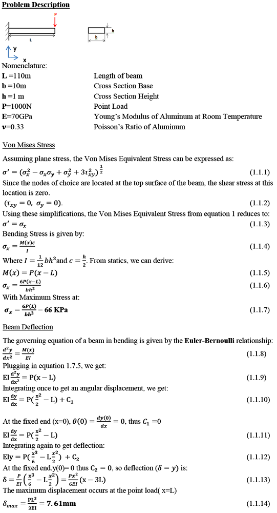
Case Study – 1: Beam – Analytical vs FEA Solution
Analytical Solution – 1D Beam subjected to Vertical loading
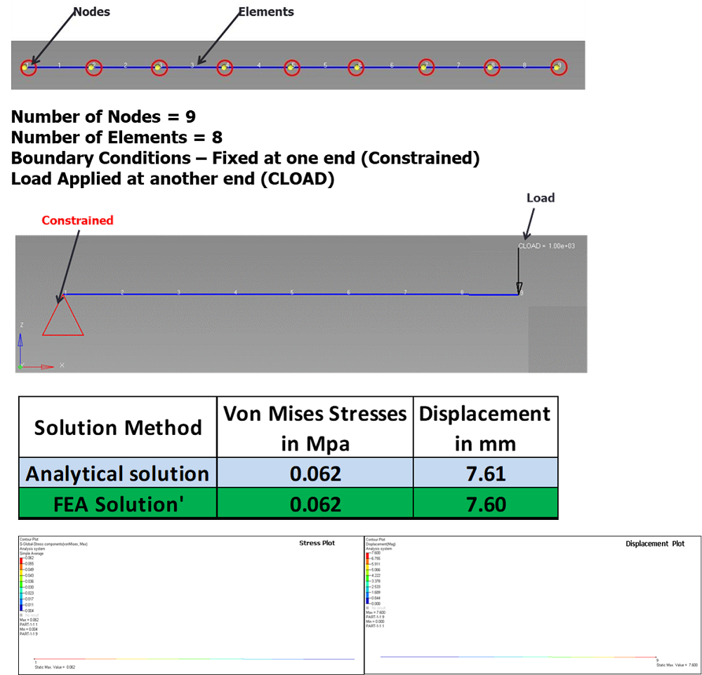
FEA Solution – 1D Beam subjected to Vertical loading
🚀 Join the Enggwave Community!
Get instant alerts for Engineering Jobs, MNC, OEM, Govt & PSU jobs and career guidance directly on your phone.
Follow us on social media for daily updates: